
General test procedures for measuring passive fire protection
When conducting fire tests, they should be conducted on loaded sections according to h BS 476 : Part 8 : 1972, Part 20 and 21: 1987. Unloaded sections should be subjected to heating system BS 476: Part 8 (1972), Parts 20 and 22, 1987.
Certified fire safety
Test specimen and steel cross-section measurement
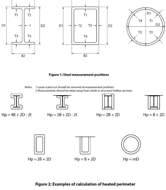
Steel sections are to be measured with the position shown in figure 1 at a minimum of 2 sections
The thickness of the steel should be measured with a tolerance of ±0.1mm and the width of each section to a ±0.5mm accuracy.
Mean values of the depth of the section (D) along with the width (B), flange or wall thickness (T), Web thickness (t), shall be noted where applicable in the report.
The section factor for a specimen is to be calculated using actual measurements of the steel, ignoring the root radii. Boxed protection systems should use the section factor from the heated perimeter. See figure 2 for more information.
Preparation and Application of specimen
Preparation techniques used with steel and the application of the fire protection system should follow that used in practice.
Specimen should be prepared as expected in practice during application. This includes the orientation of the specimen, protection of sprays and materials applied to the product (should not cover more than ±15% of the mean value), and the density of the product (should not vary by ±15% of overall mean value).
Test specimen conditioning
Regarding the strength, state of cure and moisture, the specimens should be measured to the results expected in practice. The process of identifying whether the specimen is prepared for testing involves taking a sample approximating at least 300mm x 300mm thickness and weighing regularly until its weight stabilises.
Force drying specimen (at temperatures over 300°C and humidities below 50%) should be concluded at least 2 weeks before testing to allow its weight to stabilise. The specimen shall not be tested until its weight has stabilised to within the tolerance of the sample.
If appropriate, to estimate the moisture content of a product, the sample should be oven dried at 100-1050°C, depending on the material. If applicable, drying at lower temperatures before reaching these temperatures may allow other materials to lose water content. This should be noted in the test report.
Test Procedures for Unloaded Sections
Specimen Size
Unloaded specimens should measure at 1.0m minimum height and 1.2m minimum length.
Measurement of unloaded specimens
When measuring unloaded specimens, it is important to measure using chromel/alumel thermocouples. The if the specimen needs to be held in position, the thermocouples may need to be “peened” by drilling hikes into the specimen and burring the edge of the hole. The thermocouple junction should be peened to steel plugs of the same thickness as the section wall.
The hole drilled in the section wall should have the plug secured for the thermocouple leads to run through the section. These leads should be run from the furnace without affecting the fire protection system.
Unloaded columns should be fitted with thermocouples as shown in figure 3. 5 thermocouples should be attached, with 3 on the flanges and 2 on the connecting I-section columns. Use further thermocouples if needed.
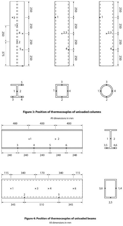
A total of 6 thermocouples will be used on the unloaded beams, 4 on the lower flange and 2 on the connecting I-section. See figure 4 for reference. Further thermocouples may be needed.
If the LPCB require examination of specific features of the fire protection system, additional thermocouples can be used.
When measuring the temperatures of the test, the unloaded specimens should be measured in intervals less than five minutes.
Application techniques.
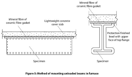
Fire protection procedures should be applied according to section 5.1.3. Additionally, the ends of unloaded specimens can be further protected to reduce end effects. Unloaded columns will be protected on 4 sides. Unloaded beams should have protection on 3 sides, with a flush end to the top of the upper flange (shown in figure 5).
Specimen Furnace Positioning
When positioning unloaded columns in a furnace, it’s important to ensure exposure to all sides. Also, with each of the columns being placed on the floor, the base should be protected with no more than 150mm material such as sand.
Also, unloaded beams are to be fitted onto the roof of the oven, along with a mineral fibre or ceramic fibre gasket attached to the top flange of the beams.
Observations
At regular intervals in testing, the unloaded columns should to checked. The observations of these specimens, with the purpose of watching for cracks or breakages, should give the basis of results for the test.
Test Termination
The test may not be terminated until the mean web and flange temperatures of each section have exceeded a 550°C limit. However, the test may be continued beyond this temperature to obtain additional information about the characteristics of the material.
Test Procedures for Loaded Sections
General
When testing loaded specimens, the BS 476: Part 8: 19721, Part 20, 21: 1987 procedures should be adopted and materials should be stressed adhering to BS 449: Part 2: 1969. Furthermore, additional procedures outside of BS 476 : Part 8 : 1972 are detailed below.
Testing the beams should be supported with a total exposed length of 4m. A concrete weight approximating 920mm x 130mm should be cast on top of the beam; this shall not greatly contribute to the strength of the beam, specifications for the method of attachment are shown below.
The columns tested with an exposed length of 3.1m. Column ends should be effectively restrained to prevent rotation but axially loaded to test properly. Details of support methods are also shown below.
Measurement of loaded specimens
While, following the BS 476 : Part 8 : 1972, Part 20, 21: 1987 requirements, thermocouple placement should follow the instructions listed in the procedures for unloaded specimens to measure temperature.
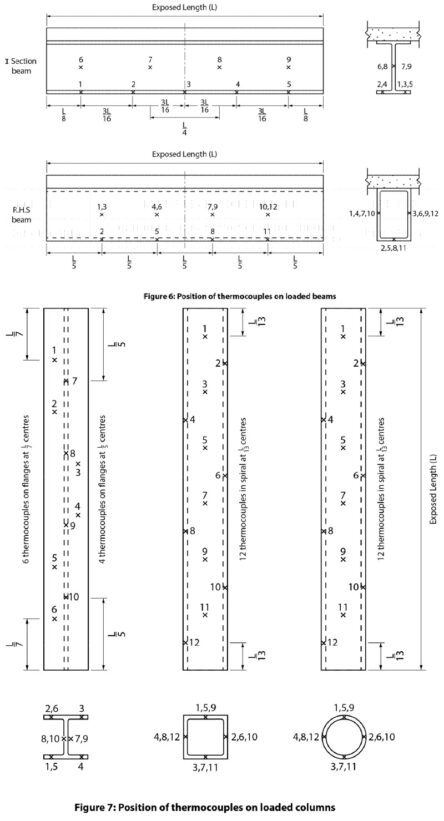
The use of 9 thermocouples on the beams should be used to fit to loaded I-section beams. Figure 6 shows 5 on the lower flange and 4 on the web. The position of these thermocouples on hollow section beams are also shown.
Additionally, 10 thermocouples should be fitted to loaded I-section columns; 6 on the flanges and 4 on the web. This along with the positioning of thermocouples to be attached to rectangular hollow section columns is shown below in Figure 7.
If the use of further thermocouples is warranted if required to test specific features of a fire protection system from the LPCB.
Application techniques
As described above in the Specimen Preparation and Application section, loaded columns should be protected on 4 sides and beams on 3 sides.
Observations
During testing, specimens should be examined regularly, ensuring that notes are taken when cracks or breakages occur.
Examining the condition of specimens at regular intervals allows for the time to take notes on the state of the material. This includes any cracks in the material or split/detached material from the specimen.
Test Termination
During testing, loaded beams should not be removed from testing until the deflection value of L/35 36, with L being the clear span. Testing the loaded column should also not be concluded until the expansion becomes negative.
Upon these limited being reached, the test may be continued, with a reduced load to gain additional data.
Website Design & Digital Marketing by Vector7 Ltd